True Zero Speed Miniature Differential Peak-
Detecting Gear Tooth Sensor IC
ATS645LSH
9
Allegro MicroSystems, Inc.
115 Northeast Cutoff
Worcester, Massachusetts 01615-0036 U.S.A.
1.508.853.5000; www.allegromicro.com
Automatic Gain Control (AGC)
This feature allows the device to operate with an optimal internal
electrical signal, regardless of the air gap (within the AG speci-
cation). During calibration, the device determines the peak-to-
peak amplitude of the signal generated by the target. The gain
of the IC is then automatically adjusted. Figure 5 illustrates the
effect of this feature.
Automatic Offset Adjust (AOA)
The AOA is patented circuitry that automatically cancels the
effects of chip, magnet, and installation offsets. (For capability,
see Dynamic Offset Cancellation, in the Operating Characteris-
tics table.) This circuitry is continuously active, including both
during calibration mode and running mode, compensating for
any offset drift. Continuous operation also allows it to compen-
sate for offsets induced by temperature variations over time.
Digital Peak Detection
A digital DAC tracks the internal analog voltage signal V
PROC
,
and is used for holding the peak value of the internal analog
signal. In the example shown in gure 6, the DAC would rst
track up with the signal and hold the upper peaks value. When
V
PROC
drops below this peak value by B
OP
, the device hyster-
esis, the output would switch and the DAC would begin tracking
the signal downward toward the negative V
PROC
peak. Once the
DAC acquires the negative peak, the output will again switch
states when V
PROC
is greater than the peak by the value B
RP
. At
this point, the DAC tracks up again and the cycle repeats. The
digital tracking of the differential analog signal allows the IC to
achieve true zero-speed operation.
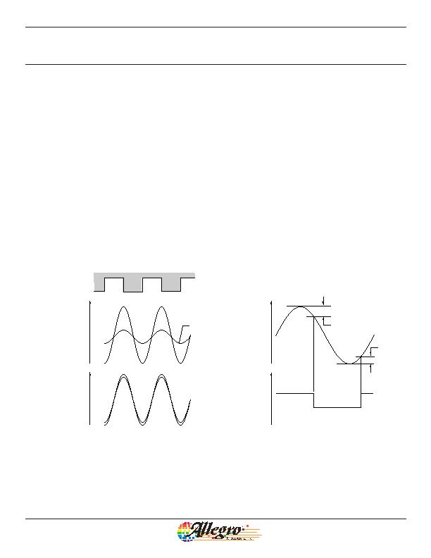
Figure 5. Automatic Gain Control (AGC). The AGC function corrects for
variances in the air gap. Differences in the air gap affect the magnetic
gradient, but AGC prevents that from affecting device performance, a
shown in the lowest panel.
Mechanical Profile
AG
Small
AG
Large
AG
Small
AG
Large
Internal Differential
Analog Signal
Response, with AGC
Internal Differential
Analog Signal
Response, without AGC
Ferrous Target
V+
V+
Figure 6: Peak Detecting Switchpoint Detail
Device
Output Current
B
RP
Internal
Differential
Analog Signal
V+
I+
B
OP
发布紧急采购,3分钟左右您将得到回复。
相关PDF资料
ATS667LSGTN-T
IC SENSOR GEAR TOOTH 4SIP
ATS674LSETN-LT-T
IC SENSOR GEAR TOOTH 4-SIP
ATS682LSHTN-T
IC HALL EFFECT SENSOR 4SIP
ATS685LSHTN-T
IC HALL EFFECT GEAR SENSOR 4SIP
BU52001GUL-E2
IC HALL EFFECT SW BIPO VCSP50L1
BU52003GUL-E2
IC HALL EFFECT SW BIPO VCSP50L1
BU52014HFV-TR
IC HALL EFFECT SW BIPO HVSOF5
BU52040HFV-TR
IC HALL EFFECT BIPO LATCH HVSOF5
相关代理商/技术参数
ATS645LSHTN-I1-T
制造商:ALLEGRO 制造商全称:Allegro MicroSystems 功能描述:True Zero Speed Miniature Gear Tooth Sensor
ATS645LSHTN-I2-T
制造商:ALLEGRO 制造商全称:Allegro MicroSystems 功能描述:True Zero Speed Miniature Gear Tooth Sensor
ATS651LSH
制造商:ALLEGRO 制造商全称:Allegro MicroSystems 功能描述:Two-Wire Self-Calibrating Differential Speed and Direction Sensor with Vibration Immunity
ATS651LSH_05
制造商:ALLEGRO 制造商全称:Allegro MicroSystems 功能描述:Two-Wire Self-Calibrating Differential Speed and Direction Sensor with Vibration Immunity
ATS651LSHTN-T
制造商:Allegro MicroSystems LLC 功能描述:GEAR TOOTH SENSOR 2-WIRE SH MODULE
ATS657
制造商:ALLEGRO 制造商全称:Allegro MicroSystems 功能描述:The ATS657 includes an optimized Hall-effect sensing integrated circuit (IC) and rare earth pellet to create a user..
ATS657LSHTN-T
功能描述:IC HALL EFFECT SENSOR 4-SIP RoHS:是 类别:传感器,转换器 >> 磁性 - 霍尔效应,数字式开关,线性,罗盘 (IC) 系列:- 标准包装:1 系列:- 传感范围:20mT ~ 80mT 类型:旋转 电源电压:4.5 V ~ 5.5 V 电流 - 电源:15mA 电流 - 输出(最大):- 输出类型:数字式,PWM,8.5 位串行 特点:可编程 工作温度:-40°C ~ 150°C 封装/外壳:20-SSOP(0.209",5.30mm 宽) 供应商设备封装:20-SSOP 包装:Digi-Reel® 其它名称:AS5132-HSST-500DKR
ATS660LSB
制造商:ALLEGRO 制造商全称:Allegro MicroSystems 功能描述:True Zero Speed Hall Effect Adaptive Gear Tooth Sensors
